Industrial Motor Condition Monitoring
Motors drive almost every process in a plant, and most of them fail slowly. Continuous vibration, temperature and electrical monitoring spots bearing wear, misalignment, imbalance and winding problems weeks before a breakdown, so repairs happen on your schedule, not the motor’s.
Keep production running, not repairing
Catch developing faults weeks ahead and fix them in a planned shutdown instead of mid-shift.
Replacing a worn bearing early costs far less than rewinding a burnt-out motor or replacing a damaged shaft.
Replace walk-around vibration readings with continuous data, so technicians visit only the motors that need them.
Running motors aligned, balanced and within temperature limits slows insulation and bearing wear.
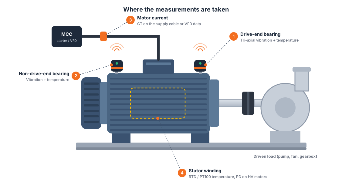
Motors are the workhorses of the plant, and a common point of failure
Electric motors run the pumps, fans, compressors, conveyors and mills that keep a plant producing, and motor-driven systems use roughly two-thirds of all industrial electricity. When a critical motor stops, the line usually stops with it.
Most motor failures are mechanical. Industry studies by IEEE and EPRI attribute around 40–50% of them to bearings, followed by stator winding and rotor faults. Nearly all of them give warning first: a change in vibration, a slow rise in bearing temperature, an imbalance in current.
Motor condition monitoring puts sensors exactly where those signals appear first, on the drive-end and non-drive-end bearings, the winding and the supply, and watches them around the clock.
The faults that stop motors, caught early
Most motor failures start as small changes in vibration, temperature or current long before anyone can hear or feel them.
Rising high-frequency vibration and bearing temperature reveal lubrication problems, pitting and spalling.
Characteristic vibration at running speed and its harmonics shows when motor and load have drifted out of line.
One-times-speed vibration and changing patterns point to unbalanced rotors, worn couplings or loose mountings.
Winding and body temperature trends expose overloads, blocked cooling and failing fans.
Current signature and phase imbalance help reveal broken rotor bars, winding asymmetry and supply problems.
On HV motors, partial discharge trends show stator insulation deterioration before it leads to a winding failure.
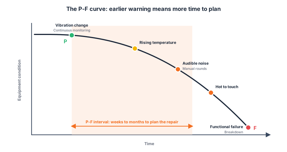
Act at the start of the P-F curve, not the end
Every developing fault follows the same path, from the first detectable change, the potential failure point (P), to the functional failure (F) where the motor stops. The earlier you see point P, the more time you have to plan the repair.
Vibration is the earliest signal for most mechanical faults. By the time a bearing is noisy or hot to the touch, which is when manual rounds usually notice it, most of that warning time is gone. Continuous monitoring catches the change close to point P, typically weeks to months before failure.
Four signals, one picture of motor health
Velocity, acceleration and spectrum (FFT) on the drive-end and non-drive-end bearings.
Bearing housing, motor body and winding temperature, compared with ambient.
Motor current and phase balance from the MCC, used to normalise readings to the load.
For medium- and high-voltage motors, online PD monitoring of the stator insulation.
Built for real plants
Health scores, trends and alarms for pumps, fans, compressors and conveyors in one view.
Rugged battery-powered sensors mount on the bearing housing in minutes, with no cabling.
Readings are compared with load and speed, which cuts false alarms on variable-duty motors.
Works on its own, feeds SCADA or BMS over Modbus RS485, or sends data to the cloud through a gateway.
Faults are ranked by severity and criticality so the most important motors are fixed first.
Alerts become work orders, and data before and after repairs confirms the fix.
 Illustrative dashboard view
Every motor’s health on one screen
Each motor gets a health score built from its vibration, temperature and current, so the maintenance team can see at a glance which assets need attention today and which can wait.
Vibration is compared with ISO 10816 / ISO 20816 severity zones and with each motor’s own baseline. When a trend crosses a threshold, the spectrum view points to the likely cause, such as a bearing defect frequency or running-speed harmonics that suggest misalignment, and the alert can go straight into a work order.
From motor to maintenance plan in four steps
Wireless vibration and temperature sensors mount on each critical motor’s bearings.
Sensors send readings over RF to a receiver or gateway; current comes from the MCC.
Trends, spectra and load-normalised baselines highlight developing faults.
Alerts and health scores become planned inspections and repairs.
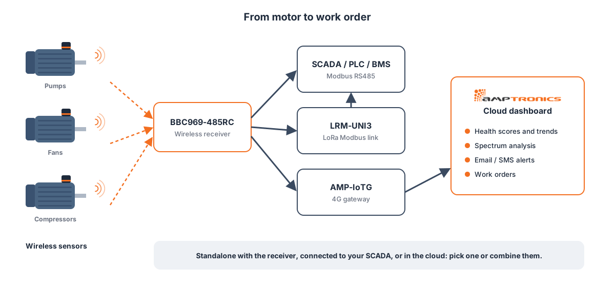
Sensors send readings to a BBC969-485RC receiver. From there, data goes to your SCADA, PLC or BMS over Modbus RS485, across the site over a LoRa link, or to the cloud through a 4G gateway, so you can start standalone and connect later.
The hardware behind motor monitoring
Tri-axial vibration plus temperature, battery-powered, magnetic or stud mount. Contact us for specifications.
Ask for details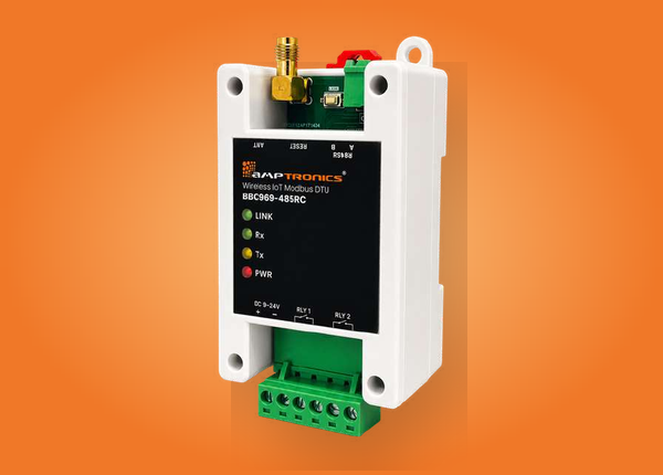
DIN-rail receiver that sends wireless sensor data over RS485 Modbus to SCADA, PLC or BMS.
View product
Carries Modbus data from remote MCCs and pump houses over a LoRa link, without new cabling.
View product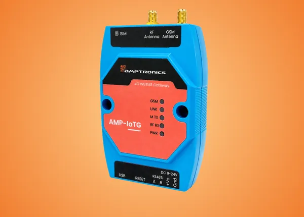
4G gateway that sends motor data to the cloud for dashboards, trends and alerts.
View productA partner from first sensor to plant-wide rollout
We design our own sensors and receivers, and we work with your maintenance team from survey to handover, so monitoring fits the way your plant already works.
Talk to an expert






Learn more from our engineering guides
Stop motor failures before they stop production
Tell us about your critical motors and we’ll help you plan a pilot that proves its value on the assets that matter most.
Book a demo Talk to an expert