Wireless Busbar Temperature Monitoring System
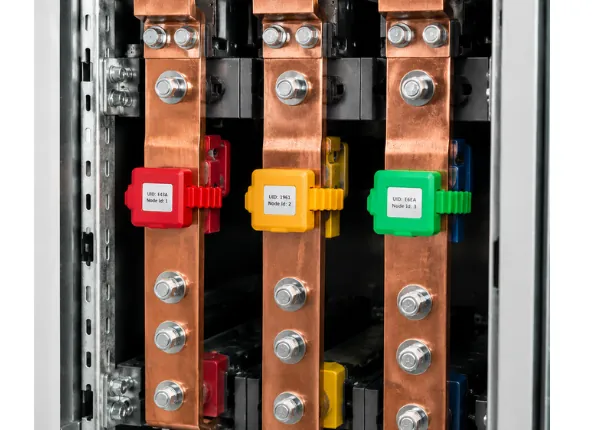
Catch hot joints before they turn into outages. The Amptronics wireless busbar temperature monitoring system watches every busbar connection inside your switchgear and bus ducts around the clock, and alerts your team the moment a temperature starts to climb.
What is a wireless busbar temperature monitoring system?
A wireless busbar temperature monitoring system (WBTMS) continuously measures the temperature of busbar joints and connections in switchgear and bus ducts using small wireless sensors, and raises an alarm when a joint starts to overheat, so it can be repaired before it fails. It replaces periodic thermography with 24/7 monitoring.
Key facts: Amptronics WBTMS- Sensors from −40 °C to 150 °C with ±0.5 °C accuracy (0–85 °C, BBS350CT)
- Battery-powered (up to 5 years) or CT-powered from the busbar current (no battery, 10-year life)
- Rated from 0.4 kV (LV) up to 66 kV (HV) switchgear and bus ducts
- AES-128 encrypted wireless link, about 10 m inside panels and 50 m line of sight
- Up to 60 sensors per controller, with alarm relays and Modbus RTU (RS485) to SCADA, PLC or BMS
- 4G cloud dashboard for live temperatures, alarms, trends and reports
Everything you need to keep busbars running cool
Continuous readings from every joint, so a loose bolt or overloaded section shows up the moment it starts heating, not at the next shutdown.
No signal wiring inside high-voltage compartments. Sensors transmit by RF to the controller, which keeps installation fast and safe.
The panel-mounted controller shows live temperature and battery status for each sensor and switches relays to drive hooters, fans or trip circuits.
Every reading is available over RS485 Modbus, so it drops straight into the SCADA, HMI or building management system you already use.
Send data through a gateway to the cloud for remote dashboards, temperature trends, analytics and alert notifications from anywhere.
Strap-on, battery-powered sensors fit new panels and existing installations alike, with no drilling or busbar modification.
What is a wireless busbar temperature monitoring system?
Busbar joints are the weakest point in any power distribution panel. Loose connections, oxidation and overloading raise contact resistance, and the heat builds up silently until insulation fails or a fire starts. Periodic thermography only gives you a snapshot, and it often means opening live panels.
A wireless busbar temperature monitoring system (WBTMS) puts a small wireless sensor on each critical joint. A controller inside the panel collects the readings, raises local alarms and passes the data on to SCADA or the cloud, so maintenance teams can act on facts instead of fixed schedules.
How a wireless busbar temperature monitoring system works
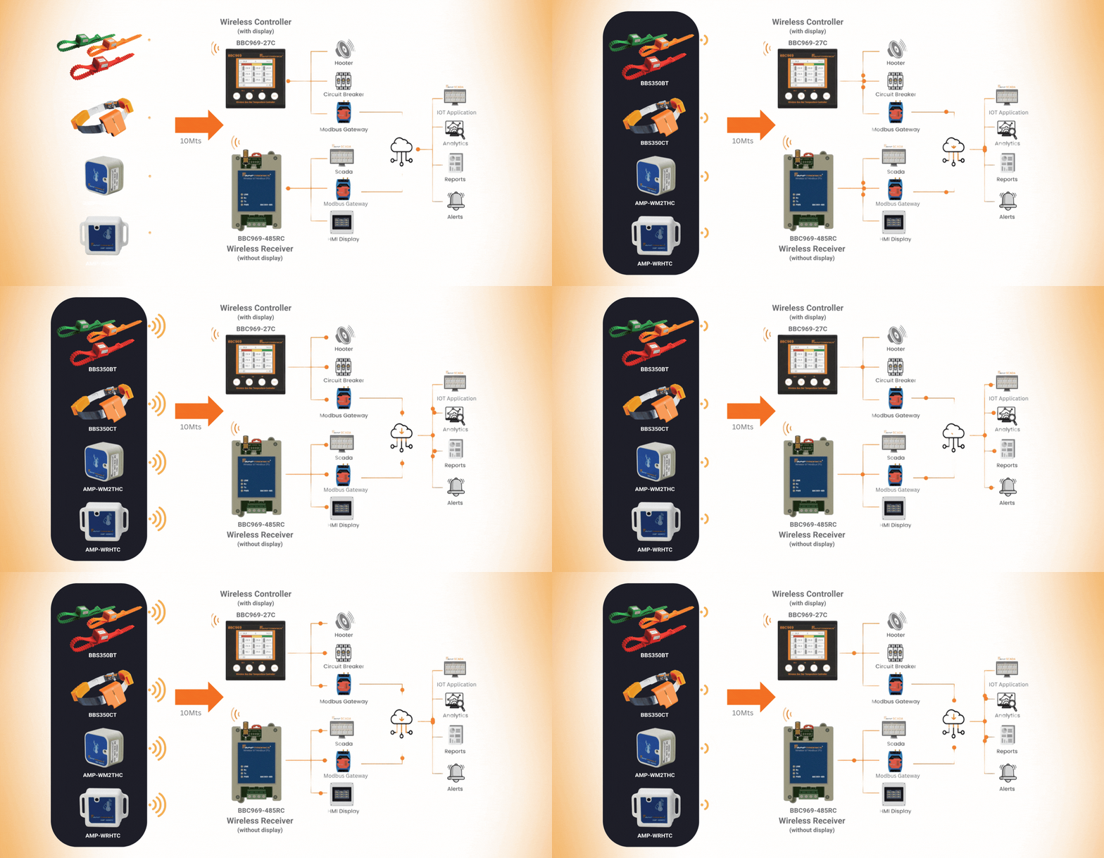
Four parts work together, from the sensor on the copper to the alarm on your phone.
Readings travel by radio with AES-128 encryption, about 10 m inside a panel and up to 50 m line of sight, so no signal wiring is run near live parts.
A BBC969-27C panel controller or BBC969-485RC receiver collects up to 60 sensors and switches relays for hooters or trip circuits.
Data goes to SCADA, PLC or BMS over Modbus RTU, or through the AMP-IoTG 4G gateway to the cloud dashboard for trends and alerts.
Why busbar joints overheat
Every bolted joint has a small contact resistance. When that resistance rises, the joint turns more current into heat, and the extra heat makes the joint deteriorate faster. Left alone, the cycle ends in melted insulation, an arc flash or a fire.
The temperature at the joint is the earliest, most reliable sign that something is wrong, which is why continuous monitoring catches problems that a yearly thermography survey misses. Read more in our guide to the 5 hotspots to check in electrical connections.
Wireless monitoring vs thermography and wired sensors
How a wireless busbar temperature monitoring system compares with the other common ways of checking switchgear temperature.
| Method | How often it checks · what you need |
|---|---|
| Manual thermography | Once or twice a year. Panels opened or IR windows fitted, a trained surveyor and a camera. Misses faults that develop between surveys. |
| Fixed IR windows | Only when someone looks. Still a manual survey, and only joints in the window’s line of sight are covered. |
| Wired sensors | Continuous, but signal cables have to be run and insulated near live busbars, which makes installation and retrofits harder. |
| Wireless monitoring (WBTMS) | Continuous, 24/7. Strap-on sensors with no signal wiring, local alarms, trends and remote access. Suits new panels and retrofits. |
The hardware in our wireless busbar temperature monitoring system
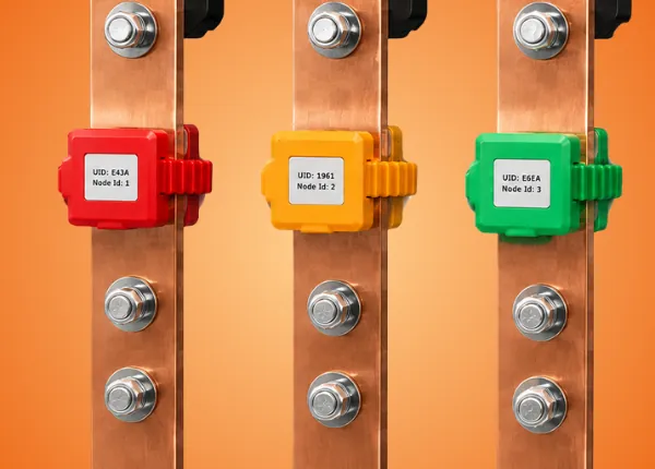
Battery-powered strap-on sensor for busbar joints: -40°C to 125°C, up to 5 years of battery life.
View product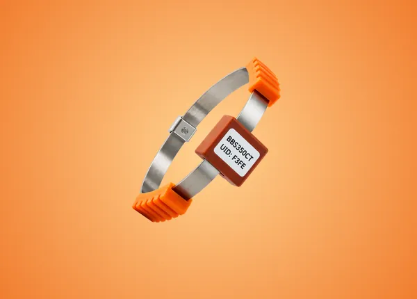
Self-powered (CT) busbar sensor: no battery, -40°C to 150°C, 0.4–66 kV.
View product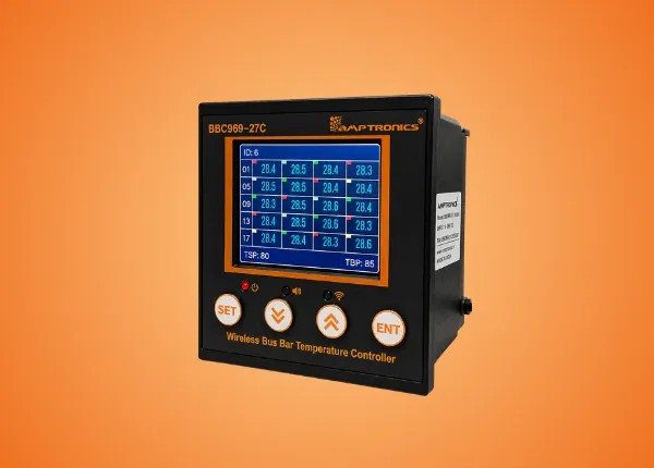
Panel-mount controller with colour display, live readings and two alarm relays.
View product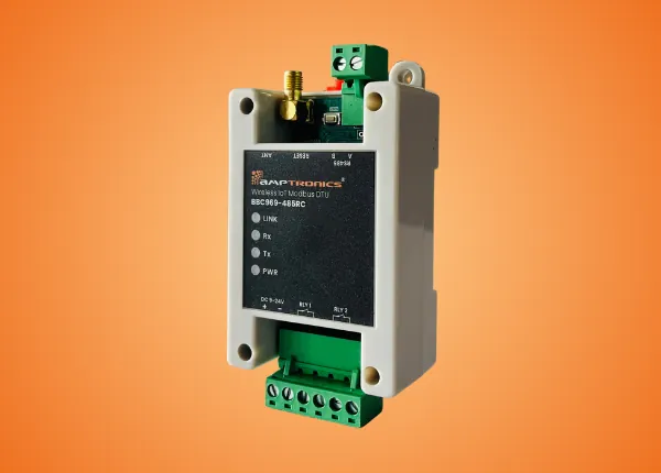
DIN-rail Modbus DTU that sends sensor data over RS485 to SCADA, PLC or BMS.
View product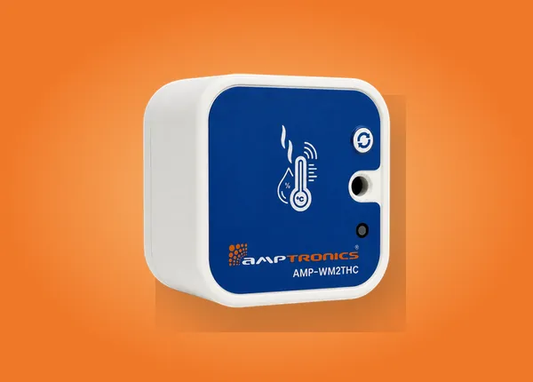
Magnetic wireless sensor for bus duct surface temperature and ambient humidity.
View product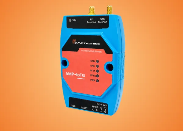
4G gateway that sends sensor data to the cloud dashboard for alarms, trends and reports.
View productWireless busbar temperature monitoring system specifications
Key figures for the sensors and controllers in the system. See each product page for full datasheets.
| Sensors | |
|---|---|
| Sensor options | BBS350BT battery-powered, BBS350CT CT-powered (starting current ≥ 4 A) |
| Measuring range | −40 °C to 125 °C (BBS350BT), −40 °C to 150 °C (BBS350CT) |
| Accuracy | ±0.5 °C from 0 to 85 °C, ±0.75 °C above 85 °C (BBS350CT) |
| Power and life | Up to 5-year battery (BBS350BT); 10-year service life, no battery (BBS350CT) |
| Voltage levels | 0.4 kV (LV) up to 66 kV (HV) with BBS350CT |
| Mounting | Strap-on: busbars, bus duct joints, breaker contacts and cables |
| Wireless link | |
| Range | About 10 m inside panels, up to 50 m line of sight |
| Security | AES-128 encrypted data |
| Reliability | ≥ 99% packet delivery under nominal conditions (BBS350CT) |
| Controllers & outputs | |
| Sensors per controller | Up to 60 busbar sensors per BBC969-27C or BBC969-485RC |
| Alarms | Two relays for hooters, circuit breakers or BMS inputs; buzzer on BBC969-27C |
| Integration | Modbus RTU over RS485 to SCADA, PLC and BMS; 4G cloud via AMP-IoTG |
| Display | BBC969-27C panel controller shows every sensor’s live temperature |
See every joint, from the panel to the cloud
Read temperatures at the panel on the controller display, in the control room on your SCADA or HMI, or from anywhere on the Amptronics IoT application.







Where to install the sensors
How to choose a system
More detail in our guide on how to choose a wireless temperature monitoring system.
Wireless busbar temperature monitoring system: frequently asked questions
What is a wireless busbar temperature monitoring system?
It is a set of small wireless temperature sensors fitted on busbar joints and other connections, plus a controller or gateway that collects the readings, raises alarms and sends the data to SCADA, BMS or the cloud. It replaces periodic thermography with continuous, 24/7 monitoring.
How are the wireless busbar temperature sensors powered?
The BBS350BT runs on an internal battery that lasts up to 5 years. The BBS350CT has no battery: it powers itself from the busbar current by induction once the current reaches 4 A, and has a 10-year service life.
How accurate is the temperature measurement?
The BBS350CT measures from −40 °C to 150 °C with ±0.5 °C accuracy between 0 and 85 °C and ±0.75 °C above 85 °C. The BBS350BT measures from −40 °C to 125 °C.
Can it be installed in existing switchgear?
Yes. The sensors strap on to busbars, breaker contacts and cables, so no drilling or changes to the busbar are needed. Installation is done with the panel safely isolated, typically during a planned shutdown.
Which voltage levels does it support?
The BBS350CT sensor is rated for installations from 0.4 kV (LV) up to 66 kV (HV), covering LT panels, MCCs, MV switchgear and bus ducts.
How many sensors can one controller handle?
Each BBC969-27C controller or BBC969-485RC receiver supports up to 60 busbar sensors, enough for 20 three-phase joints per panel.
How does the system connect to SCADA, BMS or the cloud?
The BBC969-485RC and BBC969-27C provide Modbus RTU over RS485 for SCADA, PLC and BMS. The AMP-IoTG gateway sends the data over 4G to the cloud dashboard for trends, reports and email or SMS alerts.
Is the wireless data secure and reliable?
Sensor data is encrypted with AES-128, and the BBS350CT achieves at least 99% packet delivery under nominal network conditions. Each sensor also reports its signal strength so weak links can be spotted during commissioning.
Still have questions? Read the wireless busbar temperature sensor FAQ or contact our engineers.
Learn more from our engineering guides
Ready to stop busbar failures before they start?
Tell us about your panels and we'll help you plan the right sensors, controllers and integration for your site.
Book a demo Contact sales